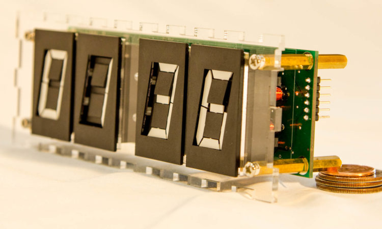
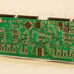
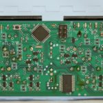
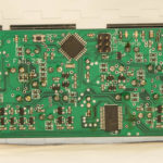
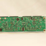
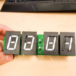
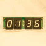
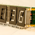
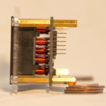
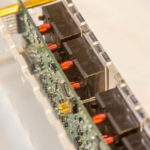
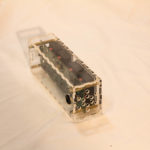
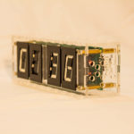
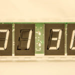
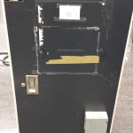
This is the official build log and walk-through for my recently completed Flip Display Clock! You can see a video of me explaining this clock here as well as a link to the associated reddit post here.
So, why design and build a Flip Display Clock? Simple – I thought it was a cool thing to make, it presents an interesting electronics challenge, and I love retro displays of all types (I’ve already built several Nixie Clocks). I was originally inspired by a reddit post of someone trying to use the same style flip digits to make their own clock; I couldn’t miss out on the fun so I purchased 6 7-segment 1″ Ferranti-Packard electromechanical displays from eBay.
These displays are electrically interesting because each segment has it’s own electromagnet which must be given a 19V 1msec ~300mA pulse in order to flip the little piece of plastic on the front from black to white. Furthermore, the coils do not have a center tap meaning that the polarity across the coils must be truly reversed to change the piece of plastic again from white to black. As each digit has 7 segments (so 7 electromagnets), and we want a 4 digit clock, the dumbest way to design the control circuitry would be to build 28 independent H-bridges. Now, a H-bridge will take a minimum of 4 transistors; all the sudden we are up to 112 individual transistors needing a ton of I/O on our MCU just to drive a 4 digit clock!
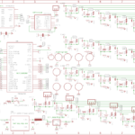
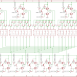
After a fair amount of thought and some recommendations from other engineers, I figured out how to multiplex the digits efficiently. They are arranged in a classic matrix configuration so I can select one of 4 digits to flip and then one of 7 segments within that digit to flip. The control electronics, only needing 11 sets now, are half-bridges (half an H-bridge). Check out schematics below.
-
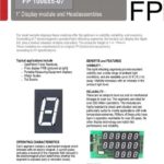
-
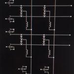
-
flip clock schematics and design
-
-
-
-
I built this clock without the diodes at first and it didn’t work. Only after some intense debugging did I realize that the diodes were needed to prevent power from energizing other segments in completely different digits than the one I was trying to control. Also, if you’re wondering why 2N2222 transistors were needed on the high side fets – this is necessary to correctly turn them on and off because they’re not ground referenced and we are making them switch 19V which is much higher than our I/O residing at 3.3V. Look up H-bridge design for more details on why this is so.
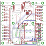
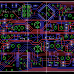
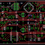
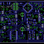
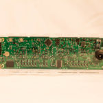
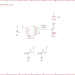
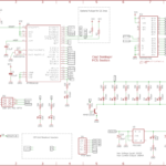
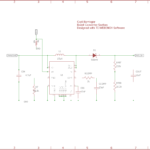
After figuring out all that needed to be done, I designed the entire circuit in Eagle PCB. The rest of the clock system is fairly straight forward. An Atmega328P micro-controller (Read Arduino) is the brains of the operation. I used a MCP23017 I/O expander to gain the necessary number of I/O needed to control all 11 half bridges described earlier (22 I/O in total for the half-bridges); this part connects to the 328P via I2C. Also on the same I2C bus is a DS3231 Real Time Clock chip with a rechargeable lithium backup battery. The only other large system on board is the 12V to 19V boost converter based on the TPS61175 chip from TI and designed with TI’s AMAZING WEBENCH software. Seriously, why would you ever design a buck or boost converter without WEBENCH in 2018?
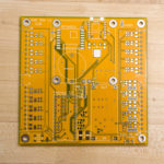
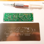
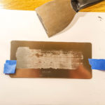
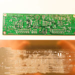
Assembly was done with my trusty DIY reflow toaster oven (I may write another post about this oven later) and a solder stencil I ordered along with the PCB from PCBway. 10 PCB’s and the solder stencil were roughly $70 including DHL shipping and they arrived in about 1 week. The pictures below show the application of solderpaste to the PCB using the stencil. After that step, each component (ordered from DigiKey) is placed with tweezers onto the PCB before the whole thing goes in the oven. I highly recommend this technique for soldering PCBs – I’ve had fantastic success with it so far. In fact, I just soldered a 6 pin BGA chip for a different project with these methods and it worked perfectly!
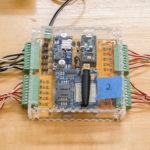
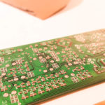
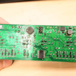
After soldering, the PCB’s look close to professional IMHO. I only had to do a couple touch ups here and there with the hot air gun. Once you’ve assembled a board like this, make sure you power it up slowly with a current limited PSU and check each voltage rail on the board as you go in case there’s a short or other problem you missed.
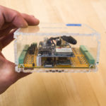
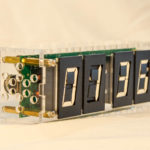
The next step was building a case. I designed an acrylic enclosure with the help of MakerCase and fine tuned the details by editing the file in AutoCAD. Once designed, I used my university’s laser cutter to cut each piece from Acrylic.
The final hardware:
Next up is software! I wrote the entirety of embedded code for this project in C/C++ with the help of the Arduino ecosystem and libraries. All development was done in the Visual Studio Code IDE with the PlatformIO plugin. If you haven’t used PlatformIO, you’re missing out! My code is attached at the bottom of this post as a zip file (too lazy to make a git repo atm) and the main program is presented here directly as well. I won’t do a very detailed walk through of my code because it’s pretty self explanatory and I tried to comment it well. At a high level, the main loop continually checks if the digits need to be updated by polling the RTC for the time and comparing it with the previously displayed time. You can also see I just used giant case statements to map out the digit I/O as it was simple and fast. Only one segment can ever be flipped at once with this clock design, but they flip very fast so it’s not a problem. The code is dependent on a few other libraries, so if you try it, make sure to get those.
// ****************************************
// Flip Clock Code V1.0
// Started: 10/26/17
// Coyt Barringer
// ****************************************
// ****************************************
// dependencies
// ****************************************
#include <Arduino.h>
//library for I2C
#include <Wire.h>
#include <DS3231.h>
//library for MCP23017 I/O expander chip
#include "Adafruit_MCP23017.h"
// ****************************************
// PIN definitions clock
// ****************************************
#define BACK_LED 13
#define WHITE_LEDS 10
//#define FRONT_TOP_LED
//#define FRONT_BOTTOM_LED
#define BOOST_ENABLE A0
#define BUTTON_A A3
#define BUTTON_B A2
#define ONET 9
#define ONEB 2
#define TWOT 7
#define TWOB 8
#define THREET 5
#define THREEB 6
#define FOURT 3
#define FOURB 4
#define AT 0
#define AB 8
#define BT 1
#define BB 9
#define CT 2
#define CB 10
#define DT 3
#define DB 11
#define ET 4
#define EB 12
#define FT 5
#define FB 13
#define GT 6
#define GB 14
#define night 22 //defines hour out of 24 hours where clock switches to night mode
#define morning 8 //defines hour out of 24 hours where clock switches to day mode
// ****************************************
// Global Variables
// ****************************************
// ****************************************
// Objects
// ****************************************
Adafruit_MCP23017 mcp;
DS3231 clock;
RTCDateTime dt;
int lasthour = 0;
int lastminute = 0;
long lastMillis = 0;
int hour = 0;
int minute = 0;
int ledMem;
bool nightFlag = false;
// ****************************************
// flipDigitTwoSegmentADown();
// ****************************************
void flipDigitTwoSegmentADown(){
//digitalWrite(BOOST_ENABLE,HIGH);
delay(1);
mcp.digitalWrite(AB,HIGH);
digitalWrite(TWOT,HIGH);
delay(1);
mcp.digitalWrite(AB,LOW);
digitalWrite(TWOT,LOW);
delay(1);
//digitalWrite(BOOST_ENABLE,LOW);
}
// ****************************************
// flipDigitTwoSegmentAUp();
// ****************************************
void flipDigitTwoSegmentAUp(){
//digitalWrite(BOOST_ENABLE,HIGH);
delay(1);
mcp.digitalWrite(AT,HIGH);
digitalWrite(TWOB,HIGH);
delay(1);
mcp.digitalWrite(AT,LOW);
digitalWrite(TWOB,LOW);
delay(1);
//digitalWrite(BOOST_ENABLE,LOW);
}
// ****************************************
// Function to flip any segment of any digit to white or black
// white = bool true
// black = bool false
// ****************************************
void flip(int digit, int segment, bool dir){
if(dir){
//flip to white
switch(digit){
case 1:
//flip certain segment
switch(segment){
case 1:
mcp.digitalWrite(AB,HIGH);
digitalWrite(ONET,HIGH);
delay(1);
digitalWrite(ONET,LOW);
mcp.digitalWrite(AB,LOW);
break;
case 2:
mcp.digitalWrite(BB,HIGH);
digitalWrite(ONET,HIGH);
delay(1);
digitalWrite(ONET,LOW);
mcp.digitalWrite(BB,LOW);
break;
case 3:
mcp.digitalWrite(CB,HIGH);
digitalWrite(ONET,HIGH);
delay(1);
digitalWrite(ONET,LOW);
mcp.digitalWrite(CB,LOW);
break;
case 4:
mcp.digitalWrite(DB,HIGH);
digitalWrite(ONET,HIGH);
delay(1);
digitalWrite(ONET,LOW);
mcp.digitalWrite(DB,LOW);
break;
case 5:
mcp.digitalWrite(EB,HIGH);
digitalWrite(ONET,HIGH);
delay(1);
digitalWrite(ONET,LOW);
mcp.digitalWrite(EB,LOW);
break;
case 6:
mcp.digitalWrite(FB,HIGH);
digitalWrite(ONET,HIGH);
delay(1);
digitalWrite(ONET,LOW);
mcp.digitalWrite(FB,LOW);
break;
case 7:
mcp.digitalWrite(GB,HIGH);
digitalWrite(ONET,HIGH);
delay(1);
digitalWrite(ONET,LOW);
mcp.digitalWrite(GB,LOW);
break;
default:
break;
}
break;
case 2:
//flip certain segment
switch(segment){
case 1:
mcp.digitalWrite(AB,HIGH);
digitalWrite(TWOT,HIGH);
delay(1);
digitalWrite(TWOT,LOW);
mcp.digitalWrite(AB,LOW);
break;
case 2:
mcp.digitalWrite(BB,HIGH);
digitalWrite(TWOT,HIGH);
delay(1);
digitalWrite(TWOT,LOW);
mcp.digitalWrite(BB,LOW);
break;
case 3:
mcp.digitalWrite(CB,HIGH);
digitalWrite(TWOT,HIGH);
delay(1);
digitalWrite(TWOT,LOW);
mcp.digitalWrite(CB,LOW);
break;
case 4:
mcp.digitalWrite(DB,HIGH);
digitalWrite(TWOT,HIGH);
delay(1);
digitalWrite(TWOT,LOW);
mcp.digitalWrite(DB,LOW);
break;
case 5:
mcp.digitalWrite(EB,HIGH);
digitalWrite(TWOT,HIGH);
delay(1);
digitalWrite(TWOT,LOW);
mcp.digitalWrite(EB,LOW);
break;
case 6:
mcp.digitalWrite(FB,HIGH);
digitalWrite(TWOT,HIGH);
delay(1);
digitalWrite(TWOT,LOW);
mcp.digitalWrite(FB,LOW);
break;
case 7:
mcp.digitalWrite(GB,HIGH);
digitalWrite(TWOT,HIGH);
delay(1);
digitalWrite(TWOT,LOW);
mcp.digitalWrite(GB,LOW);
break;
default:
break;
}
break;
case 3:
//flip certain segment
switch(segment){
case 1:
mcp.digitalWrite(AB,HIGH);
digitalWrite(THREET,HIGH);
delay(1);
digitalWrite(THREET,LOW);
mcp.digitalWrite(AB,LOW);
break;
case 2:
mcp.digitalWrite(BB,HIGH);
digitalWrite(THREET,HIGH);
delay(1);
digitalWrite(THREET,LOW);
mcp.digitalWrite(BB,LOW);
break;
case 3:
mcp.digitalWrite(CB,HIGH);
digitalWrite(THREET,HIGH);
delay(1);
digitalWrite(THREET,LOW);
mcp.digitalWrite(CB,LOW);
break;
case 4:
mcp.digitalWrite(DB,HIGH);
digitalWrite(THREET,HIGH);
delay(1);
digitalWrite(THREET,LOW);
mcp.digitalWrite(DB,LOW);
break;
case 5:
mcp.digitalWrite(EB,HIGH);
digitalWrite(THREET,HIGH);
delay(1);
digitalWrite(THREET,LOW);
mcp.digitalWrite(EB,LOW);
break;
case 6:
mcp.digitalWrite(FB,HIGH);
digitalWrite(THREET,HIGH);
delay(1);
digitalWrite(THREET,LOW);
mcp.digitalWrite(FB,LOW);
break;
case 7:
mcp.digitalWrite(GB,HIGH);
digitalWrite(THREET,HIGH);
delay(1);
digitalWrite(THREET,LOW);
mcp.digitalWrite(GB,LOW);
break;
default:
break;
}
break;
case 4:
//flip certain segment
switch(segment){
case 1:
mcp.digitalWrite(AB,HIGH);
digitalWrite(FOURT,HIGH);
delay(1);
digitalWrite(FOURT,LOW);
mcp.digitalWrite(AB,LOW);
break;
case 2:
mcp.digitalWrite(BB,HIGH);
digitalWrite(FOURT,HIGH);
delay(1);
digitalWrite(FOURT,LOW);
mcp.digitalWrite(BB,LOW);
break;
case 3:
mcp.digitalWrite(CB,HIGH);
digitalWrite(FOURT,HIGH);
delay(1);
digitalWrite(FOURT,LOW);
mcp.digitalWrite(CB,LOW);
break;
case 4:
mcp.digitalWrite(DB,HIGH);
digitalWrite(FOURT,HIGH);
delay(1);
digitalWrite(FOURT,LOW);
mcp.digitalWrite(DB,LOW);
break;
case 5:
mcp.digitalWrite(EB,HIGH);
digitalWrite(FOURT,HIGH);
delay(1);
digitalWrite(FOURT,LOW);
mcp.digitalWrite(EB,LOW);
break;
case 6:
mcp.digitalWrite(FB,HIGH);
digitalWrite(FOURT,HIGH);
delay(1);
digitalWrite(FOURT,LOW);
mcp.digitalWrite(FB,LOW);
break;
case 7:
mcp.digitalWrite(GB,HIGH);
digitalWrite(FOURT,HIGH);
delay(1);
digitalWrite(FOURT,LOW);
mcp.digitalWrite(GB,LOW);
break;
default:
break;
}
break;
default:
//do nothing
break;
}
}
else{
//flip to black
switch(digit){
case 1:
//flip certain segment
switch(segment){
case 1:
mcp.digitalWrite(AT,HIGH);
digitalWrite(ONEB,HIGH);
delay(1);
digitalWrite(ONEB,LOW);
mcp.digitalWrite(AT,LOW);
break;
case 2:
mcp.digitalWrite(BT,HIGH);
digitalWrite(ONEB,HIGH);
delay(1);
digitalWrite(ONEB,LOW);
mcp.digitalWrite(BT,LOW);
break;
case 3:
mcp.digitalWrite(CT,HIGH);
digitalWrite(ONEB,HIGH);
delay(1);
digitalWrite(ONEB,LOW);
mcp.digitalWrite(CT,LOW);
break;
case 4:
mcp.digitalWrite(DT,HIGH);
digitalWrite(ONEB,HIGH);
delay(1);
digitalWrite(ONEB,LOW);
mcp.digitalWrite(DT,LOW);
break;
case 5:
mcp.digitalWrite(ET,HIGH);
digitalWrite(ONEB,HIGH);
delay(1);
digitalWrite(ONEB,LOW);
mcp.digitalWrite(ET,LOW);
break;
case 6:
mcp.digitalWrite(FT,HIGH);
digitalWrite(ONEB,HIGH);
delay(1);
digitalWrite(ONEB,LOW);
mcp.digitalWrite(FT,LOW);
break;
case 7:
mcp.digitalWrite(GT,HIGH);
digitalWrite(ONEB,HIGH);
delay(1);
digitalWrite(ONEB,LOW);
mcp.digitalWrite(GT,LOW);
break;
default:
break;
}
break;
case 2:
//flip certain segment
switch(segment){
case 1:
mcp.digitalWrite(AT,HIGH);
digitalWrite(TWOB,HIGH);
delay(1);
digitalWrite(TWOB,LOW);
mcp.digitalWrite(AT,LOW);
break;
case 2:
mcp.digitalWrite(BT,HIGH);
digitalWrite(TWOB,HIGH);
delay(1);
digitalWrite(TWOB,LOW);
mcp.digitalWrite(BT,LOW);
break;
case 3:
mcp.digitalWrite(CT,HIGH);
digitalWrite(TWOB,HIGH);
delay(1);
digitalWrite(TWOB,LOW);
mcp.digitalWrite(CT,LOW);
break;
case 4:
mcp.digitalWrite(DT,HIGH);
digitalWrite(TWOB,HIGH);
delay(1);
digitalWrite(TWOB,LOW);
mcp.digitalWrite(DT,LOW);
break;
case 5:
mcp.digitalWrite(ET,HIGH);
digitalWrite(TWOB,HIGH);
delay(1);
digitalWrite(TWOB,LOW);
mcp.digitalWrite(ET,LOW);
break;
case 6:
mcp.digitalWrite(FT,HIGH);
digitalWrite(TWOB,HIGH);
delay(1);
digitalWrite(TWOB,LOW);
mcp.digitalWrite(FT,LOW);
break;
case 7:
mcp.digitalWrite(GT,HIGH);
digitalWrite(TWOB,HIGH);
delay(1);
digitalWrite(TWOB,LOW);
mcp.digitalWrite(GT,LOW);
break;
default:
break;
}
break;
case 3:
//flip certain segment
switch(segment){
case 1:
mcp.digitalWrite(AT,HIGH);
digitalWrite(THREEB,HIGH);
delay(1);
digitalWrite(THREEB,LOW);
mcp.digitalWrite(AT,LOW);
break;
case 2:
mcp.digitalWrite(BT,HIGH);
digitalWrite(THREEB,HIGH);
delay(1);
digitalWrite(THREEB,LOW);
mcp.digitalWrite(BT,LOW);
break;
case 3:
mcp.digitalWrite(CT,HIGH);
digitalWrite(THREEB,HIGH);
delay(1);
digitalWrite(THREEB,LOW);
mcp.digitalWrite(CT,LOW);
break;
case 4:
mcp.digitalWrite(DT,HIGH);
digitalWrite(THREEB,HIGH);
delay(1);
digitalWrite(THREEB,LOW);
mcp.digitalWrite(DT,LOW);
break;
case 5:
mcp.digitalWrite(ET,HIGH);
digitalWrite(THREEB,HIGH);
delay(1);
digitalWrite(THREEB,LOW);
mcp.digitalWrite(ET,LOW);
break;
case 6:
mcp.digitalWrite(FT,HIGH);
digitalWrite(THREEB,HIGH);
delay(1);
digitalWrite(THREEB,LOW);
mcp.digitalWrite(FT,LOW);
break;
case 7:
mcp.digitalWrite(GT,HIGH);
digitalWrite(THREEB,HIGH);
delay(1);
digitalWrite(THREEB,LOW);
mcp.digitalWrite(GT,LOW);
break;
default:
break;
}
break;
case 4:
//flip certain segment
switch(segment){
case 1:
mcp.digitalWrite(AT,HIGH);
digitalWrite(FOURB,HIGH);
delay(1);
digitalWrite(FOURB,LOW);
mcp.digitalWrite(AT,LOW);
break;
case 2:
mcp.digitalWrite(BT,HIGH);
digitalWrite(FOURB,HIGH);
delay(1);
digitalWrite(FOURB,LOW);
mcp.digitalWrite(BT,LOW);
break;
case 3:
mcp.digitalWrite(CT,HIGH);
digitalWrite(FOURB,HIGH);
delay(1);
digitalWrite(FOURB,LOW);
mcp.digitalWrite(CT,LOW);
break;
case 4:
mcp.digitalWrite(DT,HIGH);
digitalWrite(FOURB,HIGH);
delay(1);
digitalWrite(FOURB,LOW);
mcp.digitalWrite(DT,LOW);
break;
case 5:
mcp.digitalWrite(ET,HIGH);
digitalWrite(FOURB,HIGH);
delay(1);
digitalWrite(FOURB,LOW);
mcp.digitalWrite(ET,LOW);
break;
case 6:
mcp.digitalWrite(FT,HIGH);
digitalWrite(FOURB,HIGH);
delay(1);
digitalWrite(FOURB,LOW);
mcp.digitalWrite(FT,LOW);
break;
case 7:
mcp.digitalWrite(GT,HIGH);
digitalWrite(FOURB,HIGH);
delay(1);
digitalWrite(FOURB,LOW);
mcp.digitalWrite(GT,LOW);
break;
default:
break;
}
break;
default:
break;
//do nothing
}
}
}
// ****************************************
// Function to flip all segments to white
// ****************************************
void allWhite(){
delay(1);
for(int i = 1; i <= 7; i++){
delay(1);
flip(1,i,true);
}
delay(1);
for(int i = 1; i <= 7; i++){
delay(1);
flip(2,i,true);
}
delay(1);
for(int i = 1; i <= 7; i++){
delay(1);
flip(3,i,true);
}
delay(1);
for(int i = 1; i <= 7; i++){
delay(1);
flip(4,i,true);
}
}
// ****************************************
// Function to flip all segments to black
// ****************************************
void allBlack(){
delay(1);
for(int i = 1; i <= 7; i++){
delay(1);
flip(1,i,false);
}
delay(1);
for(int i = 1; i <= 7; i++){
delay(1);
flip(2,i,false);
}
delay(1);
for(int i = 1; i <= 7; i++){
delay(1);
flip(3,i,false);
}
delay(1);
for(int i = 1; i <= 7; i++){
delay(1);
flip(4,i,false);
}
}
// ****************************************
// Function to make a cool transition - ONE
// ****************************************
void coolSequenceOne(){
int delayOne = 50;
//allBlack();
delay(delayOne);
flip(1,6,true);
delay(delayOne);
flip(1,1,true);
delay(delayOne);
flip(2,1,true);
delay(delayOne);
flip(3,1,true);
delay(delayOne);
flip(4,1,true);
delay(delayOne);
flip(4,2,true);
delay(delayOne);
flip(4,3,true);
delay(delayOne);
flip(4,4,true);
delay(delayOne);
flip(3,4,true);
delay(delayOne);
flip(2,4,true);
delay(delayOne);
flip(1,4,true);
delay(delayOne);
flip(1,5,true);
delay(delayOne);
flip(1,6,false);
delay(delayOne);
flip(1,1,false);
delay(delayOne);
flip(2,1,false);
delay(delayOne);
flip(3,1,false);
delay(delayOne);
flip(4,1,false);
delay(delayOne);
flip(4,2,false);
delay(delayOne);
flip(4,3,false);
delay(delayOne);
flip(4,4,false);
delay(delayOne);
flip(3,4,false);
delay(delayOne);
flip(2,4,false);
delay(delayOne);
flip(1,4,false);
delay(delayOne);
flip(1,5,false);
delay(delayOne);
}
// ****************************************
// Function to write a number from 0 to 9 on any of the digits!
// ****************************************
void displayNumber(int digit, int number){
//makes selected digit all black before we can change the actual number on it
for(int i = 1; i <= 7 ;i++){
flip(digit,i,false);
}
switch(number){
case 0:
flip(digit,1,true);
flip(digit,2,true);
flip(digit,3,true);
flip(digit,4,true);
flip(digit,5,true);
flip(digit,6,true);
break;
case 1:
flip(digit,2,true);
flip(digit,3,true);
break;
case 2:
flip(digit,1,true);
flip(digit,2,true);
flip(digit,4,true);
flip(digit,5,true);
flip(digit,7,true);
break;
case 3:
flip(digit,1,true);
flip(digit,2,true);
flip(digit,3,true);
flip(digit,4,true);
flip(digit,7,true);
break;
case 4:
flip(digit,2,true);
flip(digit,3,true);
flip(digit,6,true);
flip(digit,7,true);
break;
case 5:
flip(digit,1,true);
flip(digit,3,true);
flip(digit,4,true);
flip(digit,6,true);
flip(digit,7,true);
break;
case 6:
flip(digit,1,true);
flip(digit,3,true);
flip(digit,4,true);
flip(digit,5,true);
flip(digit,6,true);
flip(digit,7,true);
break;
case 7:
flip(digit,1,true);
flip(digit,2,true);
flip(digit,3,true);
break;
case 8:
flip(digit,1,true);
flip(digit,2,true);
flip(digit,3,true);
flip(digit,4,true);
flip(digit,5,true);
flip(digit,6,true);
flip(digit,7,true);
break;
case 9:
flip(digit,1,true);
flip(digit,2,true);
flip(digit,3,true);
flip(digit,4,true);
flip(digit,6,true);
flip(digit,7,true);
break;
}
}
// ****************************************
// Function to write a number from 0 to 9 on any of the digits!
// ****************************************
void displayNumberStyle2(int digit, int number){
switch(number){
case 0:
flip(digit,1,true);
flip(digit,2,true);
flip(digit,3,true);
flip(digit,4,true);
flip(digit,5,true);
flip(digit,6,true);
flip(digit,7,false);
break;
case 1:
flip(digit,1,false);
flip(digit,2,true);
flip(digit,3,true);
flip(digit,4,false);
flip(digit,5,false);
flip(digit,6,false);
flip(digit,7,false);
break;
case 2:
flip(digit,1,true);
flip(digit,2,true);
flip(digit,3,false);
flip(digit,4,true);
flip(digit,5,true);
flip(digit,6,false);
flip(digit,7,true);
break;
case 3:
flip(digit,1,true);
flip(digit,2,true);
flip(digit,3,true);
flip(digit,4,true);
flip(digit,5,false);
flip(digit,6,false);
flip(digit,7,true);
break;
case 4:
flip(digit,1,false);
flip(digit,2,true);
flip(digit,3,true);
flip(digit,4,false);
flip(digit,5,false);
flip(digit,6,true);
flip(digit,7,true);
break;
case 5:
flip(digit,1,true);
flip(digit,2,false);
flip(digit,3,true);
flip(digit,4,true);
flip(digit,5,false);
flip(digit,6,true);
flip(digit,7,true);
break;
case 6:
flip(digit,1,true);
flip(digit,2,false);
flip(digit,3,true);
flip(digit,4,true);
flip(digit,5,true);
flip(digit,6,true);
flip(digit,7,true);
break;
case 7:
flip(digit,1,true);
flip(digit,2,true);
flip(digit,3,true);
flip(digit,4,false);
flip(digit,5,false);
flip(digit,6,false);
flip(digit,7,false);
break;
case 8:
flip(digit,1,true);
flip(digit,2,true);
flip(digit,3,true);
flip(digit,4,true);
flip(digit,5,true);
flip(digit,6,true);
flip(digit,7,true);
break;
case 9:
flip(digit,1,true);
flip(digit,2,true);
flip(digit,3,true);
flip(digit,4,true);
flip(digit,5,false);
flip(digit,6,true);
flip(digit,7,true);
break;
}
}
// ****************************************
// Setup
// ****************************************
void setup() {
pinMode(BOOST_ENABLE, OUTPUT);
pinMode(BACK_LED, OUTPUT);
pinMode(BUTTON_A, INPUT);
pinMode(BUTTON_B, INPUT);
pinMode(WHITE_LEDS, OUTPUT);
//keep boost converter off
digitalWrite(BOOST_ENABLE, LOW);
digitalWrite(WHITE_LEDS, HIGH);
//set all DIGIT pins to outputs
pinMode(ONET, OUTPUT);
pinMode(ONEB, OUTPUT);
pinMode(TWOT, OUTPUT);
pinMode(TWOB, OUTPUT);
pinMode(THREET, OUTPUT);
pinMode(THREEB, OUTPUT);
pinMode(FOURT, OUTPUT);
pinMode(FOURB, OUTPUT);
//set initial matrix pin outputs so everything is OFF!
digitalWrite(ONET, LOW);
digitalWrite(ONEB, LOW);
digitalWrite(TWOT, LOW);
digitalWrite(TWOB, LOW);
digitalWrite(THREET, LOW);
digitalWrite(THREEB, LOW);
digitalWrite(FOURT, LOW);
digitalWrite(FOURB, LOW);
Serial.begin(115200);
delay(10);
// Initialize DS3231
Serial.println("Initialize DS3231");;
clock.begin();
// Set clock time on first reprogram
// make sure to comment the below out so we don't reset time every time the clock restarts!!!
//clock.setDateTime(2017,11,23,10,11,00);
//flash LEDs a few times to indicate startup sequence
for(int i = 0; i <= 10; i++){ digitalWrite(BACK_LED, LOW); delay(200); digitalWrite(BACK_LED, HIGH); delay(200); } //enable I/O expander mcp.begin(); //default address 0 delay(100); //set all I/O expander pins to outputs! mcp.pinMode(0, OUTPUT); //GPA0 mcp.pinMode(1, OUTPUT); //GPA1 mcp.pinMode(2, OUTPUT); //GPA2 mcp.pinMode(3, OUTPUT); //GPA3 mcp.pinMode(4, OUTPUT); //GPA4 mcp.pinMode(5, OUTPUT); //GPA5 mcp.pinMode(6, OUTPUT); //GPA6 mcp.pinMode(7, OUTPUT); //GPA7 //LED1 //BOTTOM LED mcp.pinMode(8, OUTPUT); //GPB0 mcp.pinMode(9, OUTPUT); //GPB1 mcp.pinMode(10, OUTPUT); //GPB2 mcp.pinMode(11, OUTPUT); //GPB3 mcp.pinMode(12, OUTPUT); //GPB4 mcp.pinMode(13, OUTPUT); //GPB5 mcp.pinMode(14, OUTPUT); //GPB6 mcp.pinMode(15, OUTPUT); //GPB7 //LED2 //TOP LED //turn all segment transistors OFF mcp.digitalWrite(AT, LOW); mcp.digitalWrite(AB, LOW); mcp.digitalWrite(BT, LOW); mcp.digitalWrite(BB, LOW); mcp.digitalWrite(CT, LOW); mcp.digitalWrite(CB, LOW); mcp.digitalWrite(DT, LOW); mcp.digitalWrite(DB, LOW); mcp.digitalWrite(ET, LOW); mcp.digitalWrite(EB, LOW); mcp.digitalWrite(FT, LOW); mcp.digitalWrite(FB, LOW); mcp.digitalWrite(GT, LOW); mcp.digitalWrite(GB, LOW); mcp.digitalWrite(7, HIGH); mcp.digitalWrite(15, HIGH); delay(50); digitalWrite(BOOST_ENABLE, HIGH); delay(50); lasthour = dt.hour; lastminute = dt.minute; lastMillis = millis(); //do two extra cool sequences at startup allBlack(); coolSequenceOne(); coolSequenceOne(); } // **************************************** // Forever Loop // **************************************** void loop() { // ********** //this loop will happen every second or whatever is specified in the if statement // ********** if((millis() - lastMillis) >= 1000){
//update time from the RTC chip
dt = clock.getDateTime();
hour = dt.hour;
//24 hour to 12 hour conversion
if(hour > 12){
hour = hour - 12;
}
minute = dt.minute;
//blink led every second
//will not blink if we are in night mode
if(ledMem == HIGH || nightFlag == true){
mcp.digitalWrite(7, LOW);
mcp.digitalWrite(15,LOW);
ledMem = LOW;
}
else{
mcp.digitalWrite(7, HIGH);
mcp.digitalWrite(15,HIGH);
ledMem = HIGH;
}
//end blink led every second
lastMillis = millis();
}
// **********
// set time: if button is pressed increment minute val or rollover and update time in RTC
// **********
if(digitalRead(BUTTON_A) == 1){
//coolSequenceOne();
int tempMinute = 0;
//update time from the RTC chip
dt = clock.getDateTime();
tempMinute = dt.minute;
//this statement handles rollover of the time setting
if((tempMinute + 1) > 60){
tempMinute = 1;
}
else{
tempMinute++;
}
clock.setDateTime(dt.year,dt.month,dt.day,dt.hour,tempMinute,dt.second);
//update time from the RTC chip
dt = clock.getDateTime();
minute = dt.minute;
delay(100);
}
// **********
// set time: if button is pressed increment hour val or rollover and update time in RTC
// **********
if(digitalRead(BUTTON_B) == 1){
int tempHour = 0;
//update time from the RTC chip
dt = clock.getDateTime();
tempHour = dt.hour;
//backled will be ON if we are in PM
if(tempHour > 12){
digitalWrite(BACK_LED, HIGH);
}
else{
digitalWrite(BACK_LED, LOW);
}
//this statement handles rollover of the time setting
if((tempHour + 1) > 24){
tempHour = 1;
}
else{
tempHour++;
}
clock.setDateTime(dt.year,dt.month,dt.day,tempHour,dt.minute,dt.second);
//update time from the RTC chip
dt = clock.getDateTime();
hour = dt.hour;
//24 hour to 12 hour conversion
if(hour > 12){
hour = hour - 12;
}
delay(100);
}
// **********
//update of hour digits
// **********
if(hour != lasthour){
lasthour = hour;
//run cool routine to make display more interesting and transition on each hour!
if(nightFlag == false){
allBlack();
coolSequenceOne();
allBlack();
}
//update minutes after coolSequenceOne or else it'll take one minute for any numbers to show on minute digits
displayNumberStyle2(3,(minute/10));
displayNumberStyle2(4,(minute%10));
if(dt.hour == 0){
displayNumberStyle2(1,1);
displayNumberStyle2(2,2);
}
else{
displayNumberStyle2(1,(hour/10));
displayNumberStyle2(2,(hour%10));
}
//red backled will be ON if we are in PM
if(dt.hour > 12){
digitalWrite(BACK_LED, HIGH);
}
else{
digitalWrite(BACK_LED, LOW);
}
//test for night mode and set back leds accordingly
if(dt.hour >= night || dt.hour <= morning){
digitalWrite(WHITE_LEDS, LOW);
nightFlag = true;
}
else{
digitalWrite(WHITE_LEDS, HIGH);
nightFlag = false;
}
}
// **********
//update of minute digits
// **********
if(minute != lastminute){
lastminute = minute;
displayNumberStyle2(3,(minute/10));
displayNumberStyle2(4,(minute%10));
}
}
//asdf
Flip Digit Clock Code & Libraries (Direct .ZIP)
Flip Digit Clock Complete Schematics (PDF)
Flip Digit Clock Board Layout (PDF)
Flip Digit Clock Eagle PCB Files & BOM (.ZIP)
Flip Digit Clock pcb GERBERS for PCBWay (.ZIP)
AudoCad Drawing for Laser Cut Case (.ZIP)
Laser Cut Case Ponoko size P2 File (.ZIP)
Feel free to post any questions regarding this project!
