POVON home energy monitor Part 1: 20 Channel System
This is the story of POVON: my abandoned home energy monitor project and startup. I’m documenting my work here for the reference and benefit of others working on similar devices.
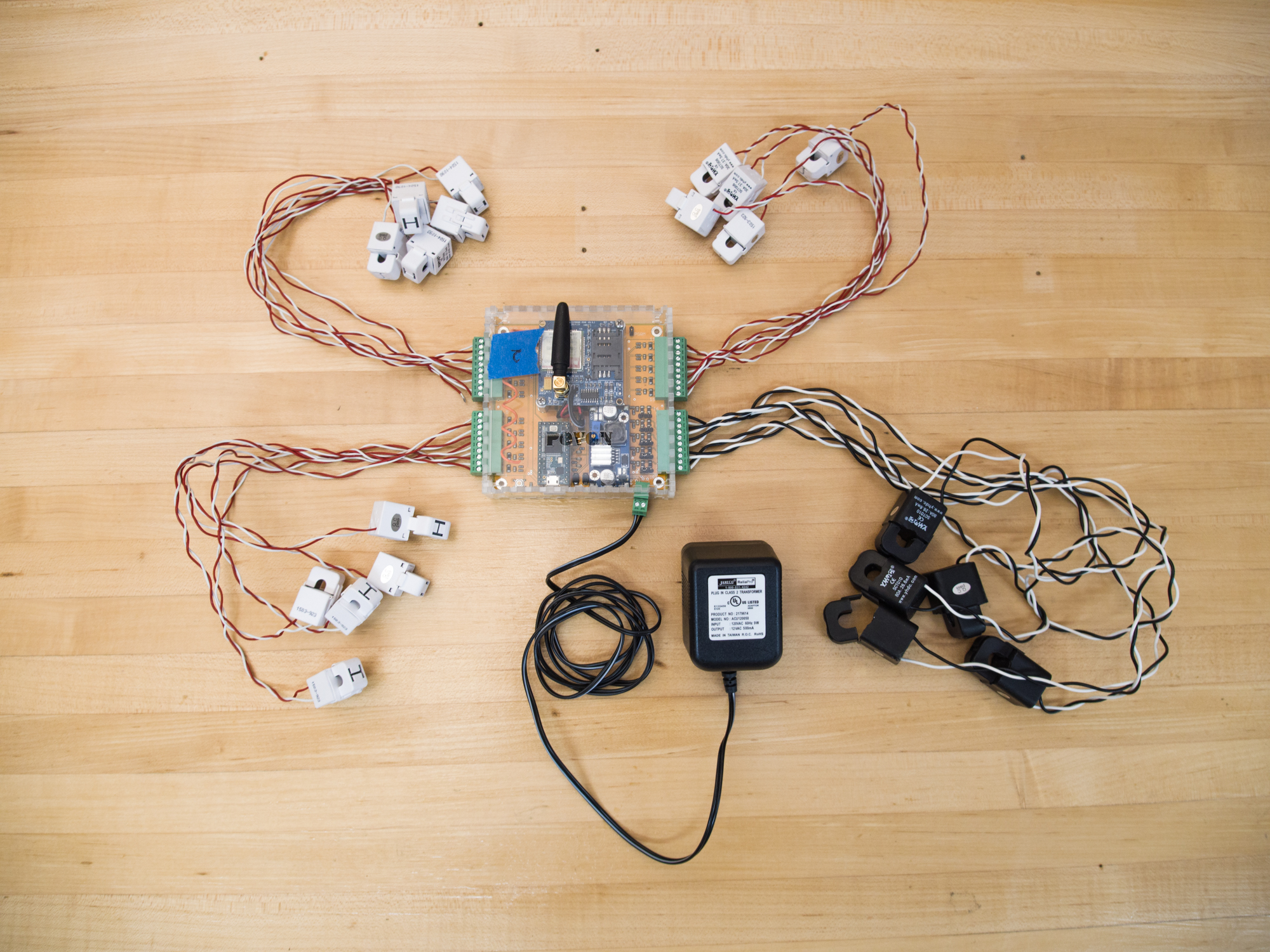
Back in 2015, myself and a coworker joined forces in an attempt to enter the “home energy monitor” market. We wanted to make and sell small home energy monitors which would live inside a household breaker-box and continuously report measurements to our web-app over the internet via WiFi or cellular connection. Unfortunately the project was more difficult than we imagined, and eventually died from neglect. I was solely responsible for the hardware design and manufacture of our systems, and two main hardware “units” were developed. This part, Part 1, will detail our 20 Channel sub-metering hardware.
20 Channel Circuit Level Home Energy Monitor Description and Overview
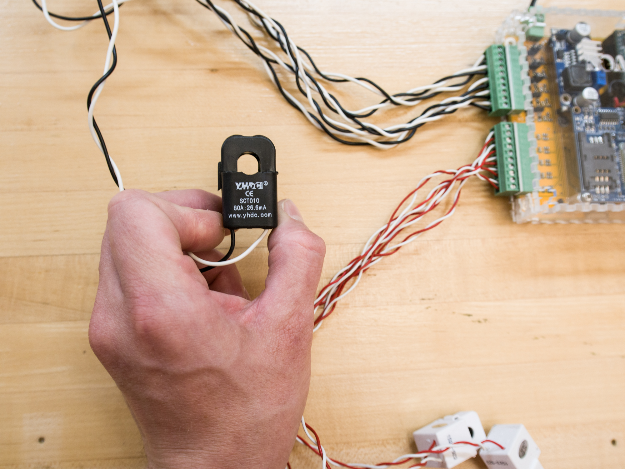
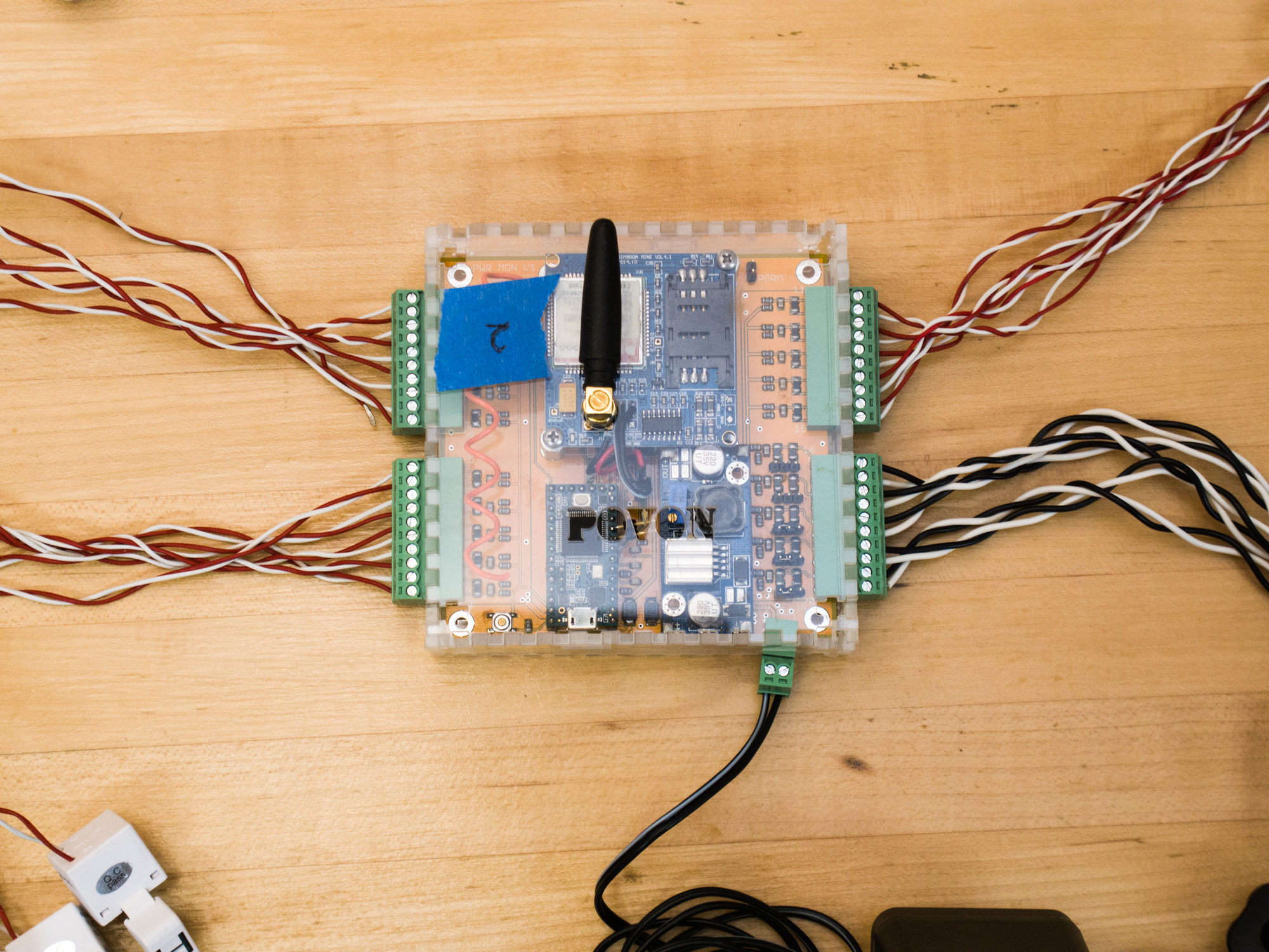
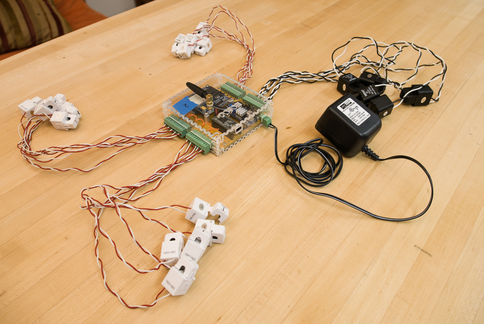
Our initial goal was to monitor power consumption in different parts of the house, and we quickly realized every household circuit would need to be monitored. After some research, small clip on current transformers, or CT’s, looked to be the best sensor for our application. Using CT’s, current draw and thus power on each circuit can be measured. The CT’s would be installed on the wires immediately leaving the circuit breakers in the standard household breaker box. CT’s work great for this because they’re completely isolated and nothing needs to be disconnected to install them. We chose Dechang Electronics model SCT-006 30A split core current transformers as our standard CT, but also implemented circuitry for up to five larger CT’s (SCT-010) for monitoring of larger 240VAC appliances. The Open Energy Monitor project has a fantastic page explaining how to connect CT’s to a micro-controller ADC pin. Alternatively, download and read my paper linked above for this.
-
- CTs for 120V appliance
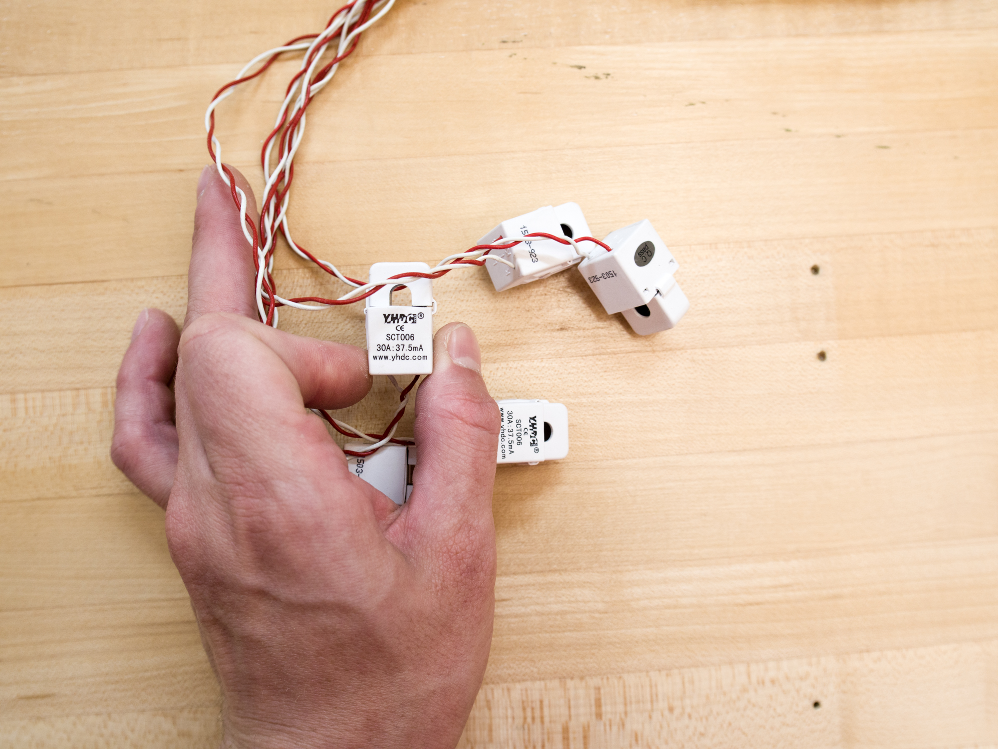
-
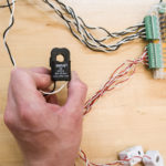
- CT for 240VAC appliance
Connectivity
Two telemetry methods were selected to report the power data back to the internet server. The first and main method was the use of the ESP8266 by Espressif, a small microcontroller with built in Wi-Fi capability. The second method is via a GSM cellular modem, specifically the SIMCOM SIM900 quad-band module. Both of these devices were selected due to their low cost (~$5 for the ESP8266 and ~$20 for the SIM900) as well as their ease of use and thorough online documentation and open source libraries. As an additional feature and the 3rd wireless device on the system, a small UHF data radio/modem (RFM69W) was added to allow for the creation of a Home Area Network (HAN).
Brains
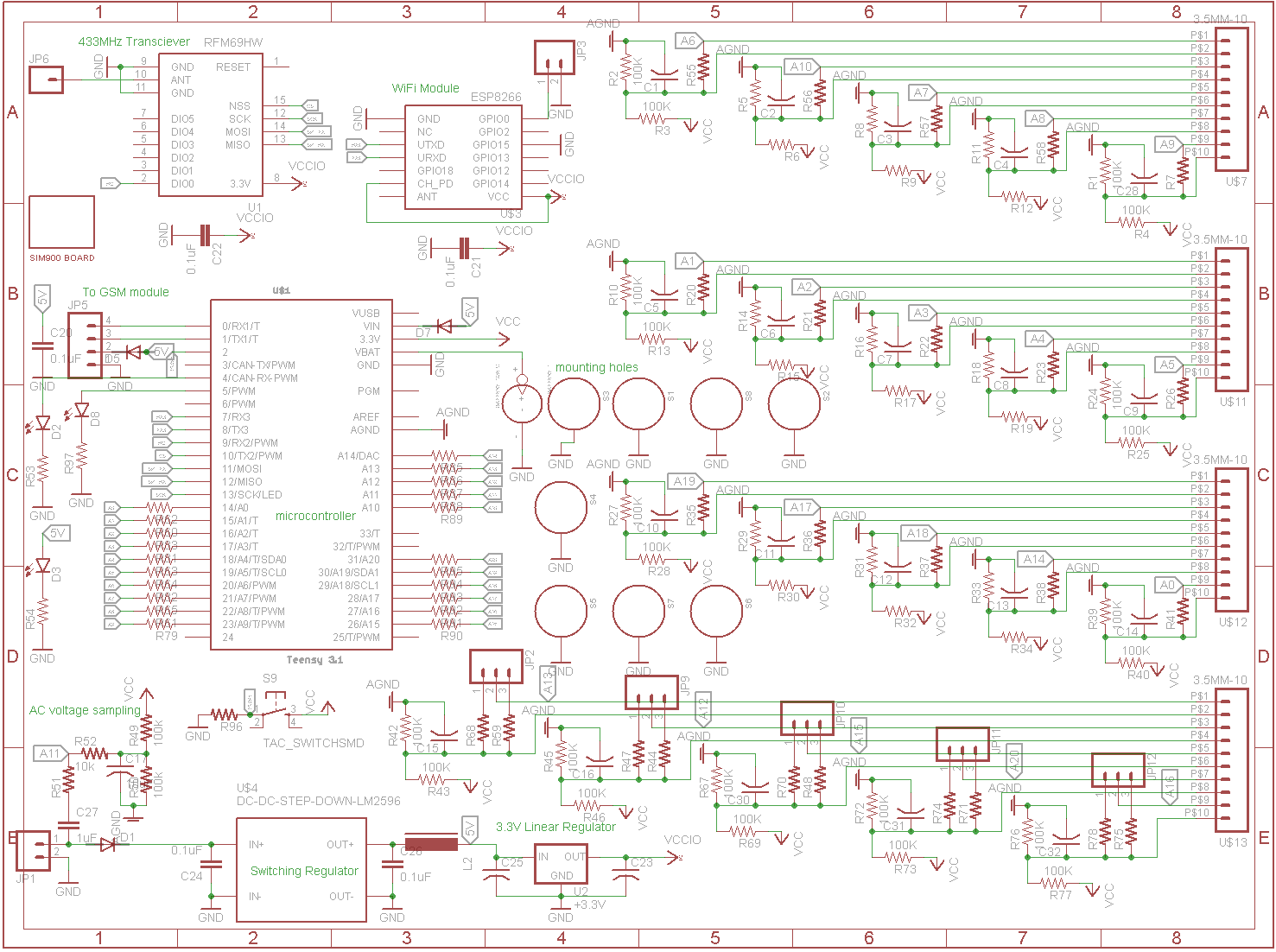
A Teensy 3.1 microcontroller was chosen as the brains of the system because the onboard MK20DX256 processor contains a decent Analog Digital Converter (ADC) capable of 2MSPS at 12 bit resolution. Furthermore, the MCU has an internal analog multiplexer allowing up to 21 pins to be routed to the ADC – the exact amount we need! (remember, we need one extra to sample the line voltage waveform!) Looking back, we should have used external discrete ADCs to measure the signals from the CTs in order to reduce interference across the PCB and obtain more accurate power measurements.
Mechanics
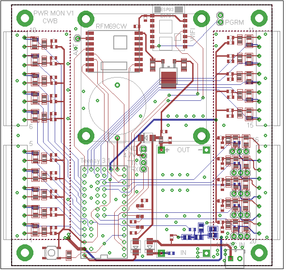
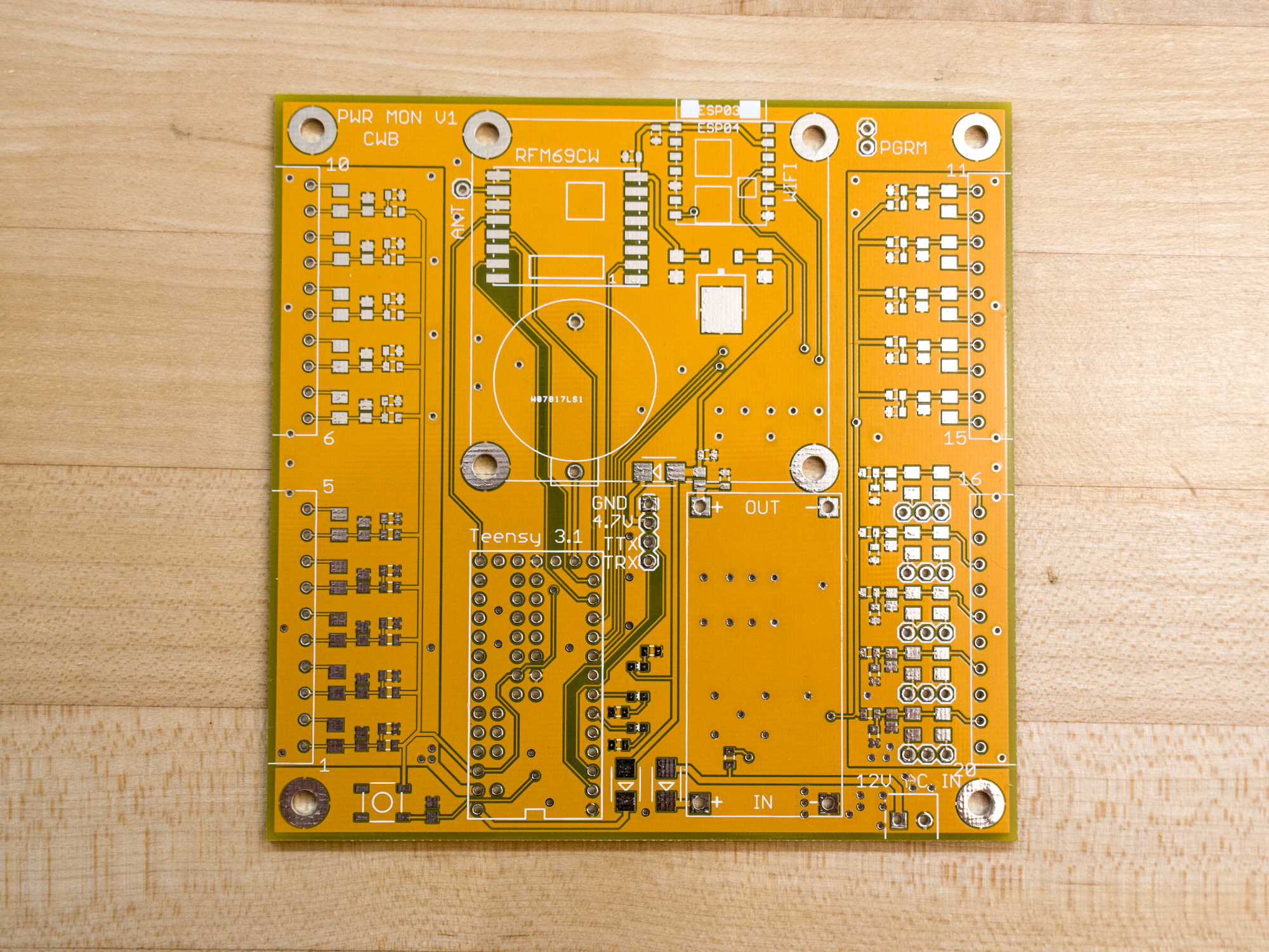
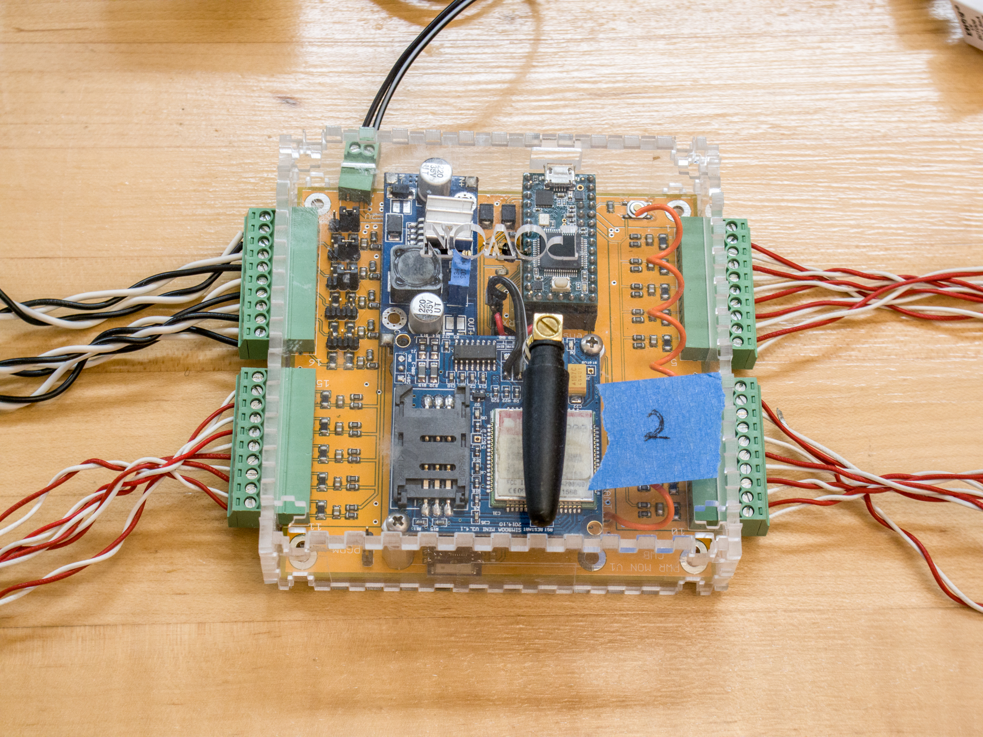
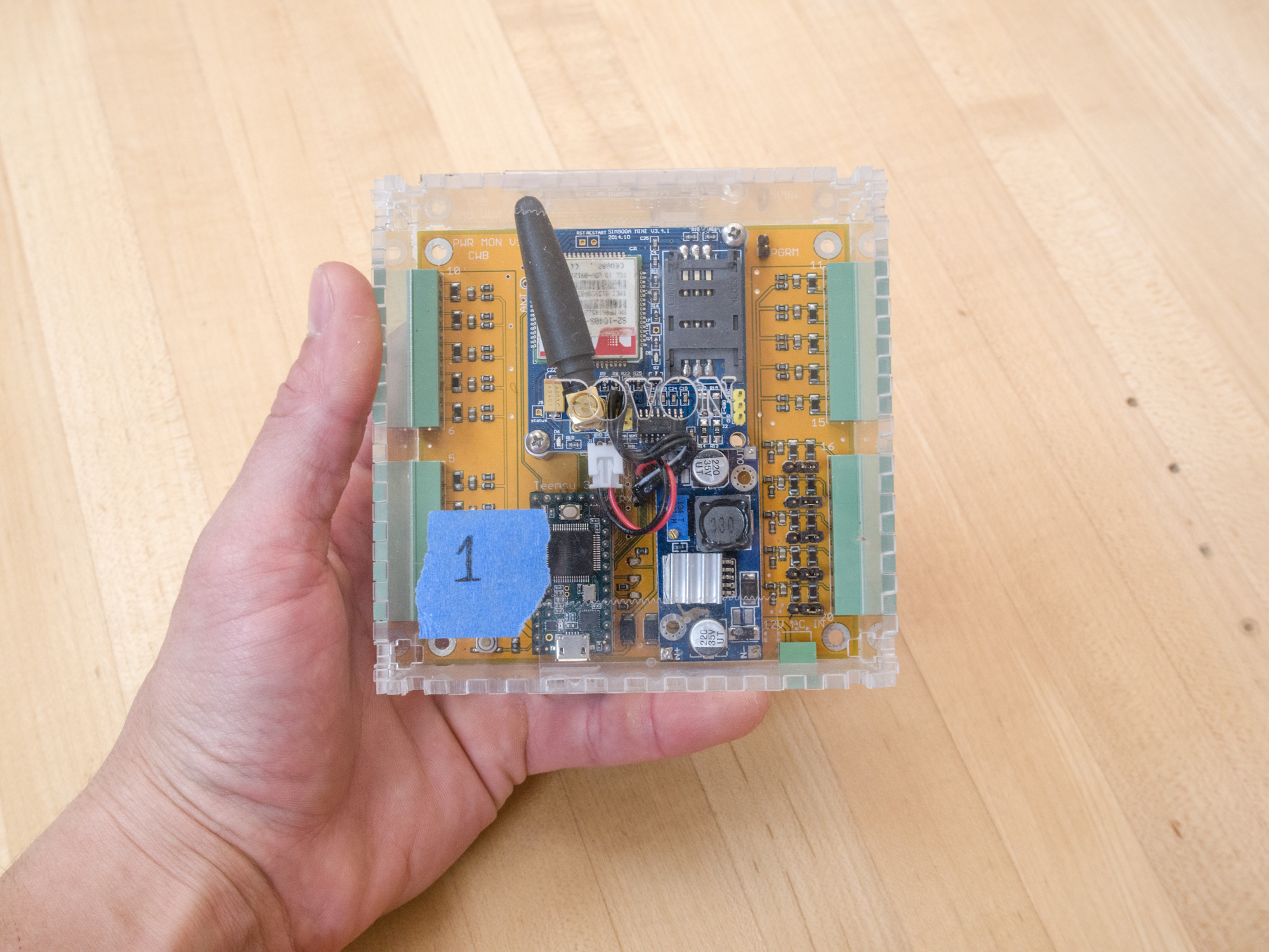
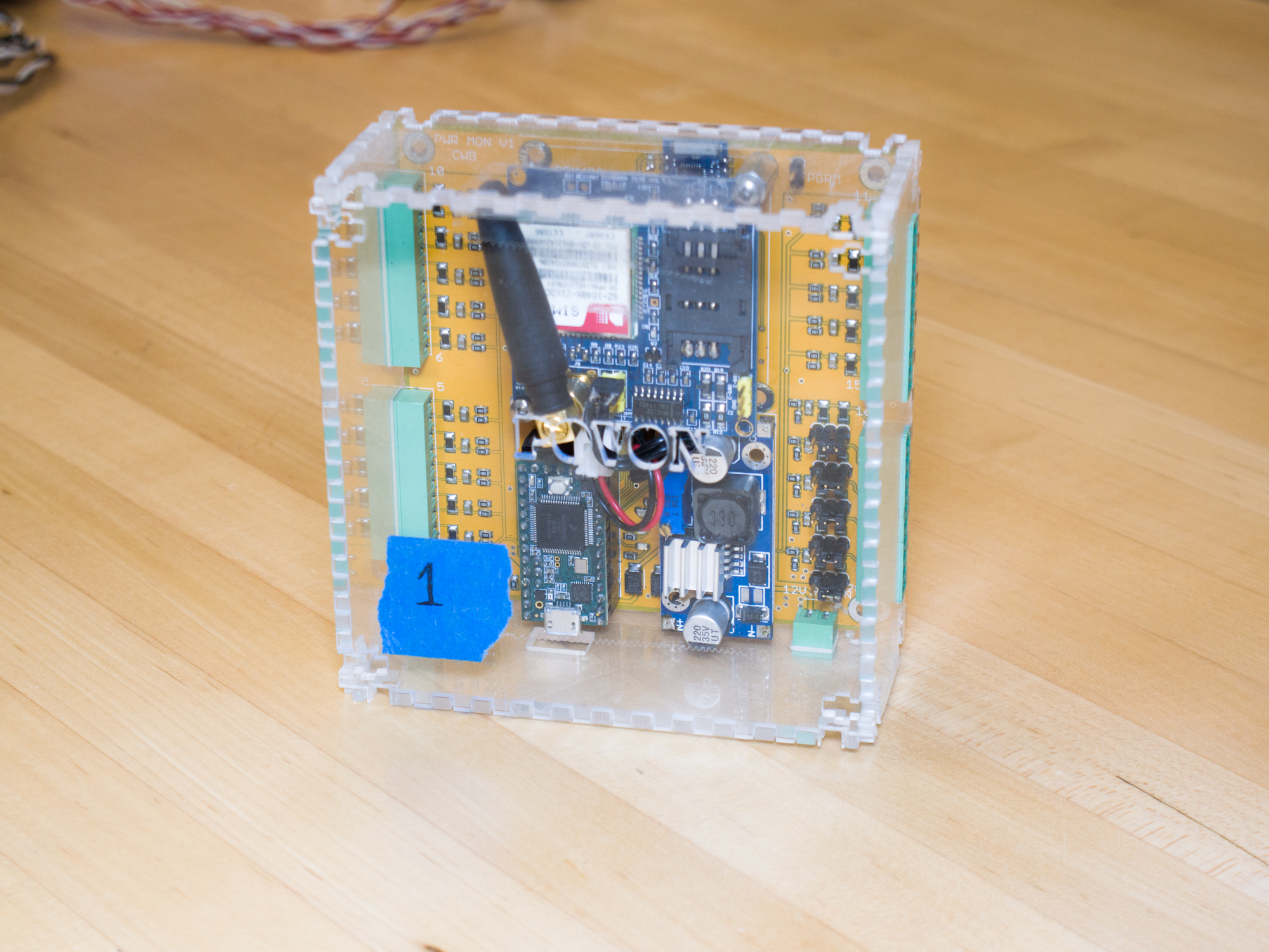
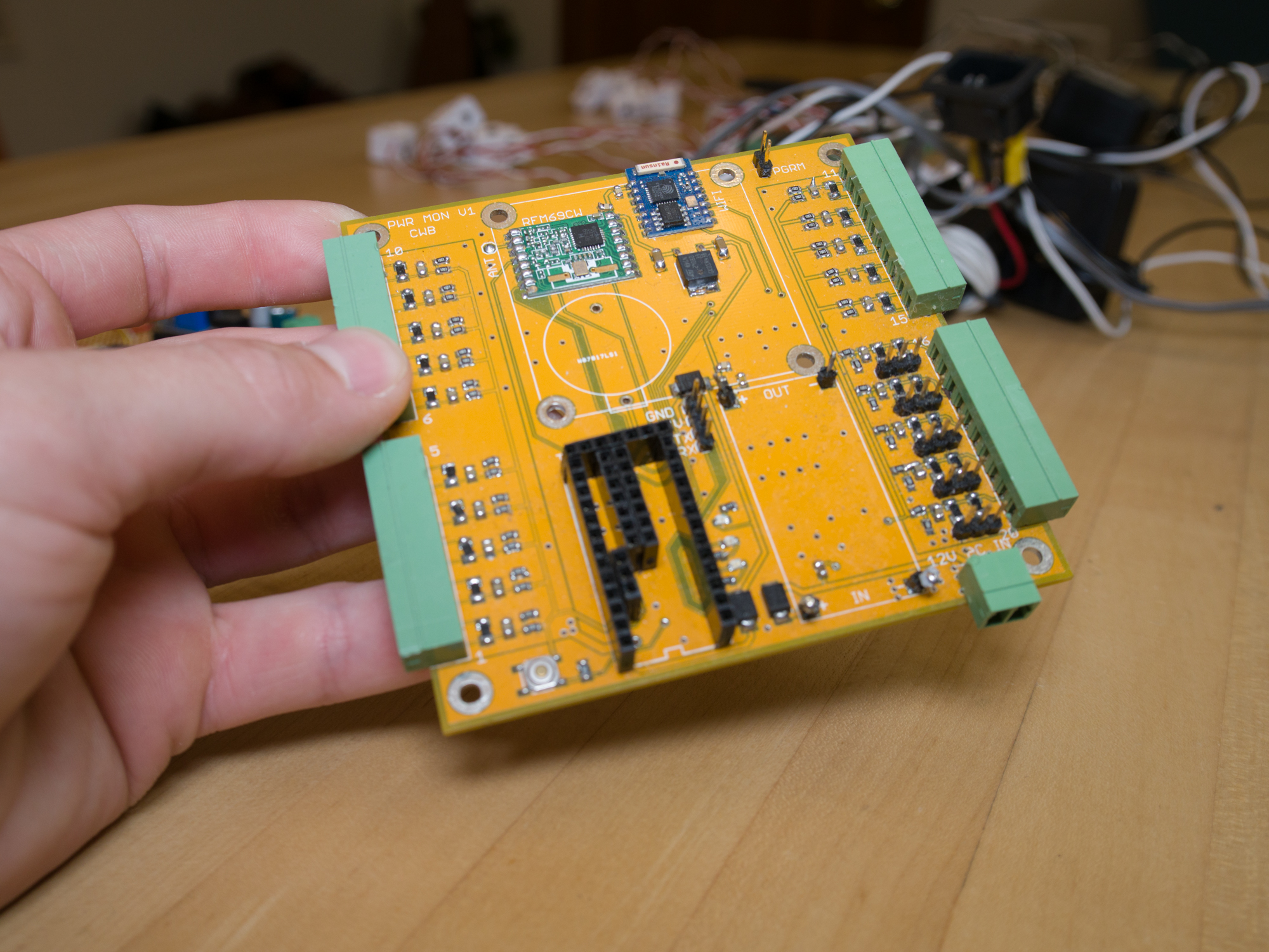
Physical and electrical design of the home energy monitor necessitated a PCB. I spun up the PCB with Eagle and had it manufactured by my favorite board-house, PCBWay. Cost was about $30 for 10 PCBs including shipping. I also made a laser cut acrylic case for the entire system. Power was supplied by a 12V AC to AC adapter – this allows the line voltage waveform to be sampled by the MCU safely for use in the power calculations. After this ADC connection, the 12V AC is rectified, filtered, and regulated down to proper levels for all board components.
-
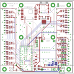
- eagle layout
-
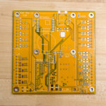
- Initial PCB
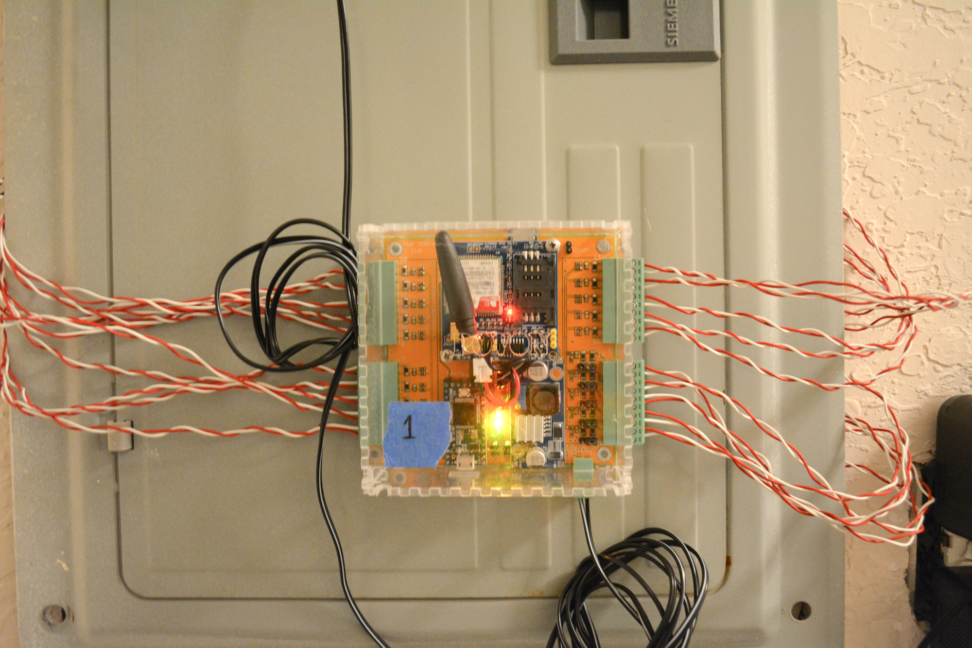
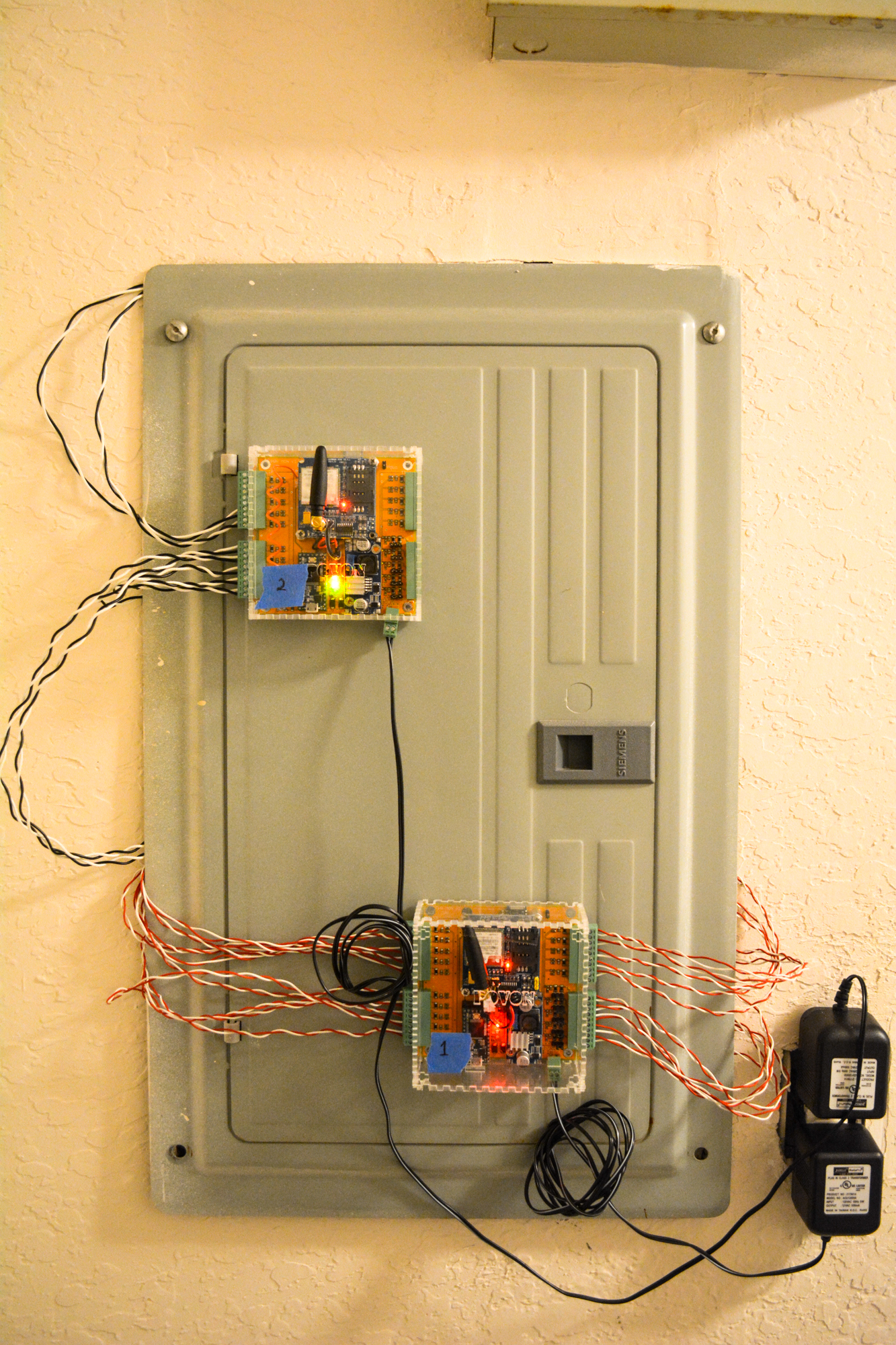
Unfortunately most of the code for this project was lost, though I’ll definitely update this page when/if I find it. This home energy monitor was installed and tested in my apartment as well as my business partner’s. We had it reporting to a server running an instance of the Open Energy Monitor web-app Emoncms successfully. Initial results were decent – readings were between 5% and 10% accurate on all 20 CT’s before any adjustments or calibrations. Please checkout the pics for more details:
Feel free to use the Eagle PCB files here (.zip warning)
Part 2 of this post, when I have time to write it up, will detail the Mini Energy Monitor

Debraj Deb
I am making an energy monitoring circuit for my house, in India. But I am not using the circuit that “emonTX” used for current and voltage sensing. The issue is that, if the 5V (or 3.3V) is removed (which is quite a possibility, when the sensors are connected, but the voltage from microcontroller is not applied, since the voltage and current sensors are both active), the DC bias of 1.65V (or 2.5V if you are using 5V microcontroller and ADC), will not be present, resulting in negative input fed into the analog inputs (which can be about -1.65V). This is way above what most ADC can handle and will result in failure. A way to avoid is to put external diodes to limit the voltage to -0.7V (or -0.3V, if using schottky diodes).